
In my previous discussions, I mentioned about a layer 2 switch being a single broadcast domain and multiple collision domain whereas a Layer 3 switch or a router is a multiple broadcast domain and multiple collision domain. So here we will learn about little bit about both these terms and in the world of Ethernet technology these terms came into picture.
Let us discuss the topics in the following order:-
- Broadcast Domain
- Collision Domain
- CSMA/CD
Collision Domain:
This terms you will commonly see in Ethernet and Wireless networks too. This term means that in a networking scenario where multiple devices are connected via shared medium and one of the devices sends out a frame on that physical network segment forcing all other devices on the same segment to listen to that communication. Other devices will not be able to send out data or frames when the physical medium is in use. This created a road block in simultaneous communication over a shared medium. Also, in case if two devices over the shared medium happens to transmit the frame at the same time, collision will occur thereby making the devices to retransmit.
Figure-a below:
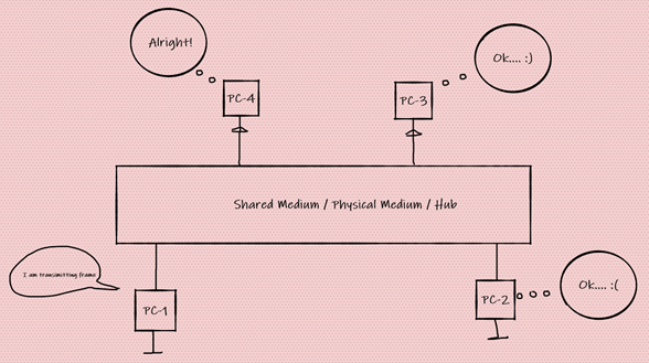
The host connected here in figure-a, are in the same collision domain. In this case if PC-1 starts transmitting, all others must wait and read the signal transmitted over the medium. Well, this kind of solution is really not going to work on modern day technology and more over we are now in a 21st century.
Since switch has each of its ports as single collision domain thereby each user can listen and simultaneously transmit frames across these medium simultaneously and there is no need to wait.

Figure-b.
Also please note switches here are considered as single broadcast domain since by default switches comes as single broadcast and if needed to have multiple broadcast domain certain configuration needs to be in place (configuration of VLAN and this type of configuration comes in later topics. This means dividing a larger broadcast domain into multiple small broadcast domain or in other words diving a large network domain).
Broadcast Domain:
This term means that a group of devices on a specific network segment that will hear and respond to all the broadcast sent out on that specific segment.
On this section, the devices communicate with each other using a Layer-2 broadcast address in the Data-Link Layer.

Figure-c
Here a switch will have one single broadcast domain by default and multiple collision domain. Whereas a Router is a multiple collision domain and multiple broadcast domain. Routers will also not forward broadcast packets out to its ports. Thus, it is said router creates broadcast domain boundaries.
CSMA/CD
Well, it stands for Carrier Sense Multiple Access with Collision Detection. This term was coined for Ethernet networking which uses CSMA/CD and using this it actually overcomes the risk of collisions which occurs due to simultaneous transmission of frames from different nodes but over the same shared medium.
Well how does this work?

Figure-d
Here if device-A wants to send a communication, first it will check over the shared medium for existing signal being transmitted. If there is no presence of signal over the shared medium then the device-A starts transmitting over the shared medium.
Next the device-A will monitor the wire to make sure no other host begins transmitting. In case the device-A detects another signal on the same wire, it will send out an extended jam signal that causes all the devices on its respective nodes to stop sending data. Refer the figure-a and figure-d for this example.
All other devices will respond to the jam signal by waiting and before doing transmitting. There is a certain algorithm that runs which will determine when the devices can start retransmitting. If collisions keep happening after 15 tries, then the node attempting to transmit will then time-out. This is half-duplex.
In case a collision does occur then it will send out a JAM signal that a collision has now occurred. This will lead to triggering a backoff algorithm where each device on the medium stops sending or transmitting for a short period of time until the backoff timer expires. This is also known as Integral wait state.
Integral Wait state-
It is a feature which allows the devices over a particular medium to be in idle state before they start communicating. This helps in avoiding collision. The point of collision occurred in the medium and the devices which are much closure to the collision will now undergo an integral wait state for a particular time. Devices which come out of the integral wait state are now able to receive and transit but the devices which are still in Integral wait state will only be able to receive but will not be able to transmit.
Communication is divided into two different categories:
a) Half-duplex – Communication happens one at a time.
b) Full-duplex- Communication happen both at the same time i.e., transmit and receive.
In full-duplex Ethernet uses two pairs of wires at the same time instead of a single wire pair like half-duplex.
Communication can further be divided into three types based with whom it wants to communication:
Unicast – One to one communication
Multicast – One to a particular group.
Broadcast – One to many in a given broadcast domain.
Ethernet Technology is a multi-access technology. The fundamental of ethernet technology is CSMA/CD where in any devices which is attached or linked to other devices using the same medium can communicate with each other at any point of time.
Lastly, CSMA/CA (Carrier Sense Multiple Access with Collision Avoidance) operates at Layer 2 (Data Link Layer) of the OSI model and is primarily used in wireless networks like those defined by IEEE 802.11 (Wi-Fi).
Unlike wired Ethernet (which uses CSMA/CD), wireless networks cannot detect collisions easily, so CSMA/CA tries to avoid collisions before they happen.
One major issue in wireless communication is the hidden node problem, where two transmitters can’t sense each other’s signals, but their transmissions can still collide at the receiver.
To help mitigate this, IEEE 802.11 defines the RTS/CTS (Request to Send / Clear to Send) mechanism, which is an optional feature used to reduce the chance of collisions by reserving the wireless medium before transmission.
Leave a Reply