
In our previous section we saw how the traffic flows between two different machines which were in the same network address. We only saw how MAC address gets exchanged within the same network.
Now we will discuss about packet flow in a network topology within a single broadcast domain and multiple collision domain. In short, we are checking the exchange of packets in a L2 device (Network Switch) and between two same LAN segment.
We are going to use the example of describing this topic with the help of IPv4. In my later section I will talk about IPv6. If you are not yet aware about what is network, IPv4 and subnetting, I have will make a brief section for these topics and you will be able to understand. The topic goes with name “What Is Network”
Setting the stage: Let us refer to the below network topology.
So, to understand our topic we will consider these two machines i.e., Machine 1(M1) and Machine 2(M2) which are both in two different LAN.
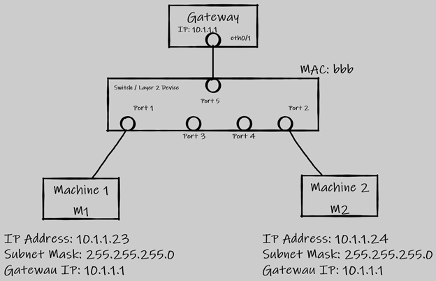
M1 has an IP address of 10.1.1.23 with a subnet mask of 255.255.255.0 or a slash value of /24 and has a Gateway address of 10.1.1.1. This machine also has a mac address of “aaa” (well I am not going to use a MAC address of 48bits for my example but if you need to know how it looks like it is this 62:70:56:bc:43:f4 and a broadcast MAC address looks like this: ff:ff:ff:ff:ff:ff).
Similarly, M2 has an IP address of 10.1.1.24 with a subnet mask of 255.255.255.0 or a slash value of /24 and it has a gateway address of 10.1.1.1. This machine also has a mac address of “ccc”.
Now we have a layer 2 device which is a switch that has one broadcast domain and multiple collision domain. The switch also has its own MAC address which is “bbb”. Although we are not going to use the switch MAC address during exchange of packets in this topic. The switch has multiple ports and user will connect their machines on any of these ports configured in the hardware.
Let us consider that M1 is connected to Port 1 and M2 is connected to Port 2. The gateway IP for M1 is configured on the Port 1 and similarly the gateway IP for M2 is configured on Port 2.
Packet Flow Begins:
When a source machine M1 wants to communicate with source machine M2 over this medium, the packets will go through the switch.
As M1 initiates a communication with M2, the packet payload will look as below. M1 will be having the IP address of the M2. In order to know how M1 will know the M2 IP address we will learn that in the DNS resolution which takes place even before the data packet is initiated by M1 to communicate with M2.
Initial Data Packet will look like from Machine 1. It is going to initiate an ARP packet since it knows the IP address of M2 but not the MAC address.
ARP Packet (Till Layer 4 header and included only Port numbers)

Note: This header expression is used only for explanation purposes. The real-life packets and frames look different with more information involve. I am showing only a sample of 20 percent from a real time packet. I will share a sample at the end of my explanation of a real packet. But the headers and fields used for explaining the purpose of a packet flow can be compared with a real time packet and yes you will find these fields in them.
Let us understand what each of this header means in simple terms.
Data Payload – This header will contain the user data information or in other words what the users are trying to access over the network.
Source MAC – It means the source MAC address of the machine. This will be a layer 2 header.
Destination MAC – This is the destination MAC address header. Sometimes we might see this header has a MAC address which looks like ff:ff:ff:ff:ff:ff and this only means that the data packet is an ARP packet where the source machine is trying to fetch the MAC address of the destination machine with whom they want to communicate. If the source machine knows the MAC address of the destination machine then it will replace the broadcast Layer 2 MAC address(ff:ff:ff:ff:ff:ff).
Source IP: This is the source IP address of the machine in a given network. This works in Layer 3 of the OSI model.
Source Port: This port is required for initiating a communication. This works at Layer 4 of the OSI Model. There is more to the layer 4 other than only port but I am not going to show here in this packet flow.
Destination IP: This is the destination IP address of the machine with which the user or the source machine will try to communicate to.
Destination Port: This is the port which will be used to communicate with the destination server. The destination server will have this port open and in listening state to accept or receive any new connection from a source on this port.
The ARP packet travels and reaches the switch on Port 1 once initiated from M1. The switch receives the packet and starts looking into the layer 2 header. The switch first looks at the Source MAC and understands that M1 has a MAC address of “aaa” and hence it stores in its CAM (Content Addressable Memory) table the MAC address of M1 against its Port 1. Now the switch will know the MAC address of M1 next time any data packets come in for M1 from any other source. The switch will also map the Source MAC address of M1 along with the Source IP address in its ARP table. There is a difference between CAM and ARP table.
Now switch will see the Destination MAC address header and it sees that the MAC address is marked as layer 2 broadcast address “fff”. Switch will immediately make a replication of the ARP packet (more than one replication) and it will send out to its all port (Port 1, Port 2, Port 3 …). Thus, switch is one single broadcast domain as it allows or forwards the broadcast packet out to all other ports except for the one which it received on. This will be a multicast message.
The broadcast as it is forwarded out to all other ports, so the M2 which is connected to the switch on Port 2. Now M2 will start opening the broadcast packet and it first looks at the source L2 Header and learns the MAC address to store in its own ARP table. It then checks the destination L2 header and notice that it is a L2 broadcast address and then proceed to check the L3 header. It learns the Source IP address of M1 and update its own ARP table and then it opens the destination IP address. It learns that M1 is trying to communicate and wants to know its own(M2) MAC address.
So now M2 accepts the broadcast packet and replies back a Unicast message. The message now becomes unicast since now M2 knows the IP address and MAC address of M1 as it was able to learn and update its ARP table from the broadcast message it received few millisecond (yes, all these communication in a fraction of second. The unicast message looks as below. Notice how the source MAC and Source IP address changed which was one under destination header. The port will remain same in this communication. The IP address for M2 comes under Source header because this M2 is replying to M1 with its own MAC address mentioned in the Source MAC address.

If there will be a machine connected to the switch on Port 3, the machine will receive the broadcast or ARP packet and will look into the layer 2 header and layer 3 header. The machine will drop the packet after looking into the layer 3 destination IP header if that IP address does not belong to itself.
Now once the switch receives the unicast message it will again open the layer 2 header and layer 3 header. It will learn the Source MAC of the M2 and the port on which it received the packet which is Port 2 and it will store the data or information in its CAM table. Switch will then see the destination MAC address and it looks up in its CAM table whether the switch already has this MAC address “aaa” or not. It comes to know that there is CAM entry for this MAC against Port 1. So, it will forward the packet directly out via Port 1. Here switch no longer finds the need to make any duplicate packet for this unicast message as the switch knows where the machines M1 and M2 are connected based on its MAC address which got exchanged in this packet flow.
Now M1 receives the reply to its ARP packet from M2. So M1 will start sending the actual data information in the data payload and will send across to M2 using the M2 MAC address. One more thing to note is that the ARP packet which will have a data payload will not contain the actual data information that M1 was trying to send to M2. The data is send in the data payload only after receiving the MAC address of M2.
Isn’t this a very simple process and all you need to know how two machine communicates with each other using a Switch.
If you have noticed in this whole flow, none of the packet goes to gateway IP or gateway device in order to communicate with each other. The reason being, both M1 and M2 are two machines in the same network with common Gateway IP address. The Gateway is the last resort for machines in that LAN network to come and communicate in case they come across any destination IP that does not belong to the same LAN IP Network (10.1.1.0/24). So, the main reason the M1 does not sends the packet to gateway is because before a machine initiates a ARP packet, it does a AND process (logic gate concept) and checks if the destination packet belongs to the same LAN segment or it belongs to a different network segment all together. After the AND process the machine decides whether the ARP packet should be going to Gateway or needs to be send to the same LAN network or segment.
Now something that I promised to show how a real time packet looks like but not deep diving in all the headers one by one. But yes, I am marking the Source MAC, Destination MAC, Source IP, Source Port, Destination IP and Destination Port here below.
In this above capture, this was simply me accessing a webpage from my web browser. Well, the important thing to take away from this capture is that whatever I tried explaining in the above section are also present in the real time packet capture. The source MAC address I have hidden for security purpose but you can see the destination MAC address too. The source port number here it is shown as 10993, this source port will keep on generating by your system operating system (OS) every time you visit a new webpage. The OS keeps a record of the session too using this source port number and this source port number selection are random.
I hope you enjoyed this content.
Leave a Reply